
Check out this video and see Travers Tool Tech Team Expert Kurt Repsher demonstrate how to read dial indicators and dial test indicators. Dial, and dial test indicators, are used for precise comparisons or measurements of workpiece surfaces, machine, equipment, part tolerances, alignment of your machine's components, or the general deviation of any object from an expected standard. Though not as easy to read as their digital counterparts, dial indicators display measurements very clearly and analog dial indicators are not reliant on batteries or a power source.
Be sure to subscribe to our YouTube Channel by clicking the button below, and check out many more exclusive 'How To' videos, product demos, unboxings and more!
What Dial indicator typeS are There?
There are two basic types of dial-type indicators:
- Dial Indicators are known by a few names. Most commonly called a Dial Indicator, they are also known as AGD Indicators (American Gage Design), or Drop Indicators, due to the way the point ‘drops’ out of the bottom of the body of the indicator. These indicators usually have a very large range of measurement, compared to the Test Indicators. The most common measuring range is 1", but some are less, and others can even be as much as a few inches. Because of the broad measuring range, they have two dials (or counters) on them. It’s usually the larger needle that counts each 0.001", with a number printed on its face at every 0.010", and they usually measure 0.100” per revolution. Since it’s easy to lose track of how many revolutions the larger needle makes, there’s also a smaller needle that counts each revolution of the larger one. These indicators are usually clamped into the holder by their 3/8" diameter stem, or by a lug mounted on the back of the body on some of them.
- Dial Test Indicators have a point that hinges, or pivots on an axis. Some will read as small as 0.0001", and they have a small measuring range, that usually goes an equal amount in both plus and minus directions from the zero. They are usually held to the indicator holders with a dovetail that fits into the holder’s clamp.
Dial Indicator vs. dial test indicator- which, when?
| Application | Dial Indicator | Dial Test Indicator |
| Measure Runout | X | X |
| Measure Height | X | X |
| Align Shafts | X | |
| Find the center of a round hole or boss | X |
What Are The Parts Of A Dial indicator?
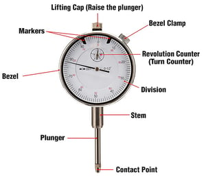
Bezel: used to rotate the zero to align with the needle
Markers: used to provide reference points
Contact Point: reads the surface of the workpiece
Plunger: transfers the point movement to the indicator
Revolution (Turn) Counter: counts each revolution of the pointer
Pointer: points to the measured number
Basic Dial Indicator Reading Terms
- Measuring Range: defines as the most distance the indicator can measure. Most have a measuring range of 1″.
- Resolution: the smallest distance it’s able to measure. It appears as the smallest division on the scale. Also called 'Graduation', most dial indicators have a resolution of 0.001″, but some are available with a resolution as small as 0.00005".
- Accuracy: how far from the exact measurement is allowable. It usually has a “±” symbol and most have an accuracy equal to their resolution value.
- For example, ±0.0001″. When your indicator has ±0.0001″ accuracy displaying a reading of 0.0007″, then the true value is somewhere between 0.0006″ and 0.0008″.
- Divisions: the circular scale is divided into several line-markings. The distance between two lines is its division.
Most 1" dial indicators’ inner scale has 10 divisions, and the outer scale has 100 divisions.
.
what do you use a Dial indicator for?
Dial Indicators don’t necessarily ‘measure’ objects, but they measure the difference from the surface of one object to the other, around a circumference, or between two or more different objects. With the many uses and different types of indicators, there is a large variety of different ways to use them. In every example though, it’s a matter of finding a zero (or ‘home’ position) and reading above or below that to come to the correct results. Below are some examples.
using a Dial indicator to measure, step by step:
TECH TIP: Mounting must be secure. Any movement, either of the indicator or the part being measured will produce inaccurate results.
how to use a dial indicator To measure runout along a shaft:
-
- Set the point on the shaft.
- Slowly turn the shaft by hand to find either the highest or lowest point.
- Set the zero to that point.
- Turn the shaft again, to see the largest reading. The result is called ‘TIR’, or Total Indicator Runout.
how to use a dial indicator To measure the straightness along a shaft:
- Set the point on the shaft at one of its ends and zero the indicator.
- Without turning the shaft, move the indicator along the length of the shaft.
- Read the measurement on the indicator.
how to use a dial test indicator To find the center of a round hole:
- Mount a Test Indicator to the machine’s spindle.
- Move the X & Y axes to locate the indicator as close to the hole’s center as possible by eye.
- Position the indicator’s point close to, but ABOVE the edge of the hole.
- With the machine not in gear, rotate the spindle and observe the distance from the indicator’s point to the edge of the hole.
- Move the X & Y axes again, as necessary until there is a somewhat consistent distance between the indicator’s point to the edge of the hole.
- Now with the indicator’s point down, inside the hole, turn the spindle to X+ and X- while adjusting the X axis until the same reading is observed on both sides.
- Repeat step #6, but with the Y+ and Y-, and adjusting the Y axis.
- Now check the full circumference of the hole to observe any movement in the indicator’s point and adjust where it’s needed.
how to use a dial indicator To measure the height of a part:
- First, we’ll need a surface plate, or you can use a smooth, clean, flat and true table of a milling machine or a drill press.
- Determine the required height of the workpiece and use gage blocks to stack up to that exact height.
- Mount your indicator into a stand that will set firmly and slide easily on the surface plate or table.
- Set your indicator to zero by using your stack of gage blocks.
- Carefully slide the gage blocks out, away from the indicator, and slide the workpiece in.
- Read the difference on the indicator.
To measure the offset of multiple parts, or multiple places within one part, use the same procedure as mentioned above, but gage blocks will not be necessary.
how to use a dial indicator To measure an angle:
- First, we’ll need a surface plate (use of crystal pink plates, flats, granite plates, or gage stands are optimal) or you can use a smooth, clean, flat and true table of a milling machine or a drill press.
- Determine the required angle of the workpiece and use gage blocks and a sine plate to obtain the exact angle.
- Mount your indicator into a stand that will set firmly and slide easily on the surface plate or table.
- Put your workpiece on the sine plate (compound sine plates, magnetic sine plates and compound magnetic sine plates are available) and set the indicator to zero at one end of the angle being measured.
- Carefully slide the indicator along the length of the angle while reading the difference on the indicator.
Want To Learn how to choose the right caliper?
Download our valuable guide on the proper selection and usage of digital, dial, and Vernier calipers. Learn the advantages and disadvantages of each, and which caliper best meets your needs and suits your application. Find information on:
- The fundamentals of calipers
- The features and appropriate use of digital, dial and Vernier calipers
- The benefits of calibrated calipers
- Ingress Protection (IP) Ratings explained