


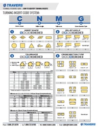
how to identify your turning insert
Making sense of the ANSI (American National Standards Institute) insert code system
Letters = shape
Numbers = size
Our example is a CNMG332 insert:
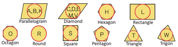
Insert Shape (CNMG332)
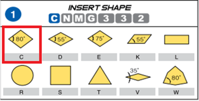
C = 80° Diamond
For a detailed breakdown of ANSI insert naming, refer to our Turning Insert Designation System Code Chart.
Edge Relief Angle (CNMG332)
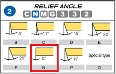
N = 0° (or ‘Negative’)
- The “N” (or 0° relief angle) insert is considered to be “negative”. All other inserts have a positive relief angle and are called “positive” inserts.
- Most negative inserts can be flipped over to use both sides, making them an economical and popular choice. See our Turning & Boring Carbide Inserts for common geometries and holders.
- An easy way to distinguish between the two is by standing the insert on its edge. If it stands straight up, it’s negative. If it leans to one side, it’s positive.
Tolerance (CNMG332)
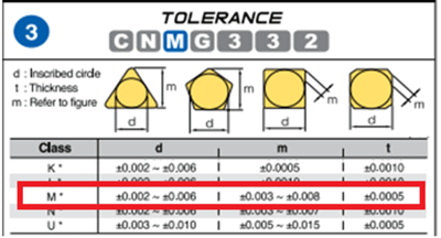
M = Looser tolerance (“molded”)
Tolerance is very difficult to measure, but any letter in this position (third letter) will work in any toolholder, if the other letters and numbers are correct.The most common letters for tolerance are G and M.
- “G” = Ground and has a tighter tolerance.
- “M” = Molded and has a looser tolerance.
Cross Section (CNMG332)
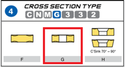
G = Hole; no countersink
Chip breaker; Double sided
- From here we’re going to move from the letters (insert shape) to the numbers (insert size).
- We’ll use the ANSI (American National Standards Institute) insert code system, or “inch” sizes.
- The “ISO” (International Organization for Standardization) is metric, so as you’ll notice below, those areas are shaded.
INSCRIBED CIRCLE OR I.C. (CNMG332)
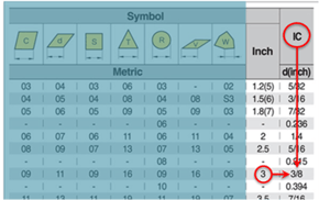
The Inscribed Circle, or I.C., is the LARGEST circle possible within the insert.
- If you refer to our Downloadable Insert Identification Chart, the shaded area is metric, or 'ISO' (International Organization for Standardization). In this example, the I.C. of an insert with a '3' in this position is 3/8"
Height of cutting edge, or thickness (CNMG332)
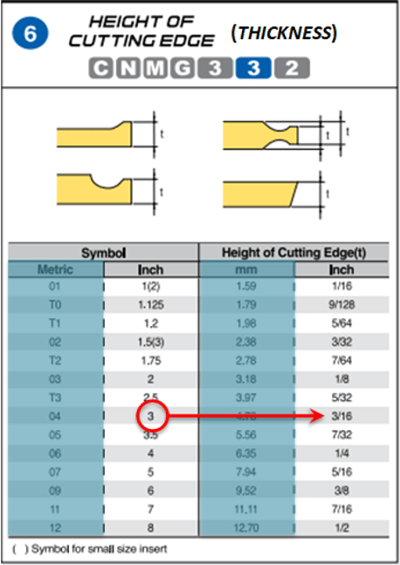
- Measuring the height of the cutting edge is difficult.
- Measuring the thickness is much easier.
- Round your result to the nearest fraction in 16ths.
- Again, the shaded areas are metric, or “ISO” (International Organization for Standardization) In this example, the Height Of Cutting Edge, or Thickness, of an insert with a '3' in this position is 3/16".
Nose Radius, or Corner Radius (CNMG332)
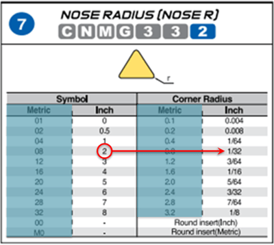
The corner radius can be hard to measure with common measuring tools, depending on the radius size.
- If you use calipers or something similar, and you measure the diameter, it’s important to reduce that measurement down to a radius, as a corner diameter will be twice the corner radius you’re looking for.
- Any number in this position (last number), will fit the holder, and is more of a personal choice, based on the operation and requirements of the work being performed.In this example, the Nose Radius of an insert with a '2' in this position is 1/32".
For threading applications, explore Thread Turning Tools: Different Styles & Holding Methods to understand holder compatibility.
EXAMPLES:
SCGT3(2.5)2
- SCGT3(2.5)2: “S” = Square
- SCGT3(2.5)2: “C” = 7° Relief Angle
- SCGT3(2.5)2: “G” = ‘Tolerance’ (ground, tighter tolerance)
- SCGT3(2.5)2: “T” = Chip Breaker, Hole and Countersink
- SCGT3(2.5)2: “3” = 3/8” I.C.
- SCGT3(2.5)2: “2.5” = 5/32” Thickness
- SCGT3(2.5)2: “2” = 1/32” Point, Corner Radius, or Nose Radius
TPG431
- TPG431: “T” = Triangle
- TPG431: “P” = 11° Relief Angle
- TPG431: “G” = Tolerance (ground)
- TPG431: “Nothing” is in the fourth position, so this space can be left blank, or it could have an “N” (TPGN).
- TPG431: “4” = 1/2” I.C.
- TPG431: “3” = 3/16” Thick
- TPG431: “1” = 1/64” Point, Corner Radius, or Nose Radius
Explore our selection of Indexable Inserts & Blades and Indexable Cutting Tools to find the right fit for your application.
For proper maintenance and secure assembly, see How To Torque A Clamp Screw On Indexable Tooling.
DowNload your guide TO insert code & Identification
the most handy, easy to use insert Identification reference!
 We've compiled a guide that helps you 'break the insert code' and easily identify your indexable inserts! Download your key to understanding the insert code system, the same reference our tech team utilizes on support calls and while machining themselves!
Our FREE Insert Identification Guide includes comprehensive reference tables and examples that list what each place of an insert name represents and identifies, including:
- Insert Shape
- Relief Angle
- Tolerance
- Cross Section Type
- Inscribed Circle (I.C)
- Height Of Cutting Edge (Thickness)
- Nose Radius

