


OPERATIONAL CONSIDERATIONS:
To determine the workholding needs of a machining operation, consider part size, material, machine speed, feed rate, and the number of parts to be produced. Single part or low quantity production typically requires a single vise setup. The part configuration will point toward either contoured jaws or any number of standard or special jaws. The gripping area for the planned operation must allow for sufficient depth of jaw engagement (bite) to safely allow the planned operation to take place.
Higher quantity production makes multiple vise setups optimal. The workpiece size determines the spacing between the vises as well as the vise size itself. Generally, attempts must be made to produce the maximum amount of parts per cycle. Many additional operations by the same operator can then be done simultaneously. The key to freeing the operator is quick clamping and the highest efficiency of the workpiece loading cycle. This includes prepping the work area for thorough chip flushing and cleaning.
SIMPLE VS. COMPLEX:
|
Workholding For Simple Machines: |
Workholding For Complex Machines: |
|
For simple machines including knee-type mills, lot sizes are small and setups are constantly required. Under these circumstances, a versatile workholding system employing vises will save considerable time. To reduce downtime, quick change jaws have been developed, which, in some cases can reduce changing jaw plates to just 5 percent of the previously required time. Making full use of the vise accessories available to you can further reduce set-up time and increase your vise's versatility. |
As the acquisition cost of a complex machine like a horizontal or vertical milling center rises, so does the burden and the need to keep the machine from sitting idle. Part loading time and setup are an integral element of downtime and require attention to maintain high efficiency. Workholding again becomes a central element in maximizing machine “up time”. Planning and completing as many operations in one clamping, and making full use of any vise accessories available can further reduce set-up time and increase machine “up time”. |
![]()
RECOMMENDED VISE MAINTENANCE:
TO MAINTAIN YOUR KURT VISE'S PERFORMANCE, AND PROTECT YOUR INVESTMENT FOR YEARS TO COME, THE FOLLOWING IS RECOMMENDED:
Daily/Weekly Vise Maintenance:
-
Clear away all machined chips in and around the vise bed.
-
Visually inspect all screw brush seals for cleanliness.
-
Air-dry & apply rust inhibiting oil to the top surface of the vise bed.
Monthly Vise Maintenance:
-
Visually inspect for chip entrapments as applicable.
-
Visually inspect all screw brush seals for cleanliness. All vises have a brush seal in the nut on the handle end of the vise.
-
Some vises have a brush seal on both ends of the nut. These brushes “sweep” chips from the screw threads.
-
Air-dry and apply rust inhibiting oil to the top surface of the vise bed. Completely open and close the movable jaw, the applied oil will help keep rust from forming in and underneath closed areas and lubricates the threads in the nut.
Vise Maintenance Every 6 to 12 Months:
-
Open the vise until you are able to insert the long of a hex wrench into the socket head set screw in the backside of the movable jaw. (Note: the backside of the movable jaw has (3) tapped holes.)
-
Loosen the setscrew but do not remove. Turn out until the face of the setscrew is approximately 1/4" to 3/8" beyond the backside of the movable jaw.
-
With the hex wrench still in place, lift upward allowing the movable jaw to pivot off the nut. Note: There is a segment in the shape of a half ball in the movable jaw cavity, be careful not to misplace while cleaning. Remove all chip guards.
-
Clean out any chips that may have built up underneath the movable jaw in the center ways of the vise bed.
-
At the end of the vise with the hex screw, remove the spiral-retaining ring (earlier style vises used a threaded collar). Slide forward the nut and screw assembly exposing the thrust bearing assembly. Remove bearing assembly and re-apply bearing grease.
-
Inspect brush seals and or wiper seals. Remove any chip build up.
-
Re-assemble screw and nut assembly installing the retaining ring. You may need to pull up the nut assembly to get the retaining ring into the groove by lifting upwards at the angled portion of the nut.
-
Oil all exposed surfaces of the screw and add a small film to the top surface of the vise bed.
-
Apply a generous amount of grease into the cavity of the removed movable jaw and place the half moon segment back in place. Align flat approximately to the same angle of the nut. The flat surface will match up with the angle of the nut once reassembled.
-
Reinstall the moveable jaw assuring the segment is properly in place
-
While pulling back on the moveable jaw, pull it against the segment and re-tighten the set screw.
-
Once the setscrew is tightened, back it out approximately 1/8th of a turn. This setscrew must not be tightened all the way down. If jaws move hard, loosen set screw another 1/8th turn.
-
Close movable jaws tightly. This will 'set' the segment to its proper orientation alignment. Open the movable jaws and re-check the setscrew for proper tightness. Again, do not over tighten.
SUMMARY
Travers Tool's technical support team can share best practices and recommendations for a variety of tooling and machining applications. Following the aforementioned recommendations can increase the longevity of your vise and ensure proper, reliable performance. Contact our tech team at 800.234.9985, utilize our website's chat feature, or email tech@travers.com for more information.
Download your Vise Maintenance Guide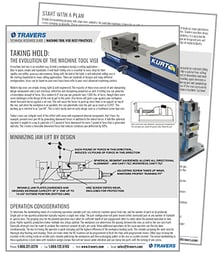
- Printable reference for daily, weekly, monthly and annual vise maintenance
- Workholding best practices for simple vs. complex machines

