
 While machining you may experience unwanted vibration when the cutting tool engages the workpiece, called ‘chatter’. Chatter in machining can be harmful and detrimental to both productivity and the life of your tools and machinery. Eliminating chattering can generate better parts, provide greater tool life consistency, and can even eliminate scrapped parts.
What is chatter in Machining?
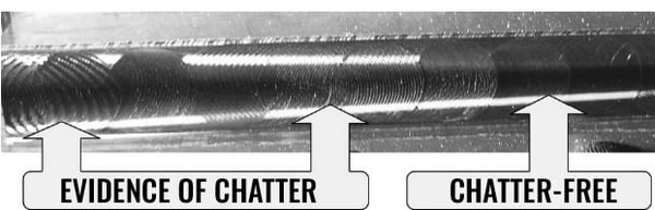
During a cutting process, there is a dynamic interaction between the cutting tool, the workpiece, and the machine tool. Chatter is a harmonic imbalance between the cutting tool and the workpiece, meaning the components are literally bouncing against each other. The cutting forces exerted by the tool on part set up will lead to resonance, eventually progressing to self-induced vibrations. The chattering may generate loud noises and may even produce a visual ‘waviness’ on the part surface being machined. This is the result of an uneven surface from the tool machining with varying cutting loads per rotation. Two other types of vibrations encountered during machining are ‘Free Vibrations’ (caused by impact forces like the sudden motion reversal of worktable during rapid traverse), and ‘Forced Vibrations’ (which results from the vibratory motion of intermittent cutting of a multi tooth milling cutter or rotation of a part mounted off-centre on lathe).
What are the consequences of chatter in machining?
- On a workpiece, it will unfavorably affect surface finish quality and geometric tolerance of parts. In some cases, it may cause possible deformation of geometric shape.
- At times it may put extra demand on workholding structures like fixtures by having to incorporate an extra degree of rigidity to withstand additional forces caused by vibration.
- It may cause excessive or uneven wear on cutting tools which may lead to premature breakages and thus compromising process security. Going further such breakages may jeopardize future reconditioning possibilities or usability of remaining cutting edges resulting in higher consumable cost.
- Persistent vibrations may cause damage to dynamically moving parts of a machine including the gears, bearings, guide ways and spindle assembly, leading to their higher wear and tear. Chatter may eventually affect long term geometric and/or positioning accuracy of a machine tool contributing to additional repair cost.
- Machinists most commonly respond to chatter by cutting back on speeds, feeds, depth of cut or by reprogramming a tool path. This impacts the optimum metal removal rate, leads to loss of productivity, and compromises overall efficiency. In cases like high speed machining, it restricts the fullest exploitation of the machine and cutting tool capability.
Different elements of the cutting process such as the cutting tool, toolholder, workpiece and machine tool have a varying degree of stiffness which effect the dampening characteristics exhibited during the cutting process. When such a structure is being subjected to excessive cutting forces, it leads to dynamic instability of the cutting process. For example, too slender of a tool or workpiece responds differently to the same set of cutting conditions than their relatively beefy counterpart. Though it maybe not always possible to eliminate chatter in machining, there are ways to minimize it by addressing each element.
Workholding
Workholding methods like fixtures, clamping tools etc. demand attention to inhibit chatter. Their design should offer overall structural rigidity to workpiece encompassing critical areas while supporting weaker part features such as slender cross sections or thin bottoms. Fixture layout and structure should consider the direction of probable cutting forces to provide adequate damping as well as stiffness. Clamping should be robust enough to deter micro movements generated due to excessive cutting forces. Once you settle on a tool path, secure the workpiece as rigidly as possible. This might be as simple as using a high-quality milling vise like the Kurt DX6 outfitted with vise jaws, or gripping the workpiece with serrated teeth vs. using smooth jaws or machining dovetails in the workpiece for extra gripping force.
Cutting Tools
Cutting tools have a major influence in chattering, and in many cases, act as a primary trigger point. As mentioned earlier, cutting tools are also one of the first things that are altered when the vibrations begin, typically via a reduction in speeds & feeds or by changing the tool outright. Therefore, the selection of the right tool for a given application can never be emphasized enough. Some things to keep in mind when choosing cutting tools are:
- Knowing when to use a solid carbide end mill vs. an indexable tool
- Using a serrated edge (knuckle) vs. a straight edge cutting tool
- For solid carbide tooling, using unequal spaced flutes and variable helixes
- Using stub tooling versus tooling with longer depth of cuts
- For indexable tool, selecting an insert with smaller nose radius, sharper cutting geometry, more positive rake angle, thinner PVD coated to even sharper uncoated inserts or a combination of these tool features
- Choosing a tool with entering angle closer to 90° or lead angle closer to 0°
- For stationary applications, checking tool setup for incorrect center height or lack of rigid clamping inside tool block also helps to eliminate chatter
Milling involves having multiple teeth simultaneously in contact with the workpiece during a cut, with each facing continuously changing chip load. Selection of the right cutter pitch based on factors like workpiece material and design, fixture rigidity etc. ensures that the right number of teeth are engaged in the application. The incorrect number could possibly lead to a harmonic imbalance. Simple solutions like reducing your radial depth, using a serrated or rougher cutting geometry, or simply choosing a tool with shorter cutting flutes produces immediate, chatter-free results. For assemblies with long tool overhang, high feed milling with the lowest entry angle is recommended, as this reduces radial-deflecting forces.
Tool Holding
Toolholders, whether stationery or rotating, are a vital link between cutting tool, workpiece and machine tool. Selecting a holder with a shortest possible overhang and a largest possible diameter is proven solution to minimize vibrations; even custom (i.e. tapered) tool design also works out as an option where setup permits its use. For lathe tools, most rigidity issues come from internal boring applications. Toolholder materials affects static stiffness and damping behavior during cutting. Steel bars works best for length to diameter ratio up to 3:1 or max up to 4:1. When overhang lengths exceed this, using high density material like heavy metal or carbide boring bars deliver good results.
During milling operations another important aspect to consider is the runout or total indicated reading (TIR). During high speed machining (HSM) applications the highest run-out precision is critical, it has a great impact on chip thickness and load distribution on each cutting tooth. A high runout could increase cutting load on one tooth vs. the remaining, increasing vibrations and in difficult to machine materials, decreasing tool life. End mill holders are the easiest to use and have one of the best ways in preventing an end mill from ‘pulling out’, but end mill holders tend to have the most runout, which can make them less productive in high speed milling operations. ER collet holders, along with high quality ER collets, can be an accurate way to hold a tool concentrically but during high speed milling operations, can have a tendency for the tool to ‘pull-out’. Heat shrink systems and mechanically locking power milling chuck systems can help alleviate this. Heat shrink systems are very accurate but require an expensive machine to heat the tooling up and each tool is limited to one shank size. Mechanical power milling holder utilize a combination of collets and mechanical bearings to securely hold tooling and can also hold runout ≤ 0.0002” well above 10,000 RPM.
Generally, during high-speed milling operations, many machinists want their runout under 0.0003” at the shank of the tool. With numbers this small, you want to make sure your spindle, collets and holders are clean so there is minimal interference between the cutting tool + holder + machine tool. For longer connections between tool tip and spindle face, try to keep as bare minimum as possible, particularly in case of modular tooling assemblies. For high performance machining applications requiring higher depth of cuts and feed, securely clamped rigid tools perform the best with the least amount of chattering. When applications are prone to extreme radial forces, tool holders offering taper, as well as face contacts, are particularly resourceful.
Milling Strategies That Give Your Mill A Thrill 
Controlling excessive radial cutting forces is a key element to reducing regenerative vibrations. Machining strategies like trochoidal and peel milling, based on chip thinning principles, will often help to reduce tool deflection and improve productivity. In the majority of cases, opting for a climb milling method helps to reduce chatter as well. To mill pocket corners or arcs, using a smaller diameter tool and programming it to required drawing radius, thus controlling arc of engagement in single or multiple passes, aids in reducing chatter. On the other end of spectrum, sometimes too low chip thickness makes the cutting edge rub part surface as opposed to cutting it, causing vibrations and possible work hardening of the affected area. Increasing feed per tooth based on the cutting edge helps to navigate past such situations. A general rule to machining is to keep chip load constant or cutting edges continuously engaged in cut to minimize entry/exit shocks. In order to achieve this, suitable entry methods such as ramping, helical interpolation, tangential or radial entry at reduced feed rate are quite handy. It is best to avoid positioning the cutter in center of cut during milling and instead should be positioned off-center while keeping cutter engagement max up to 60%-70% of diameter whenever possible. Part features with slender cross sections need extra care while choosing order of operations and programming their tool paths in order to avoid removing too much material too soon.
Summary
In a nutshell, chatter in machining leads to substantial loss of productivity and may equally affect workpiece quality, performance and life of the cutting tool and machine tool as well. The key to mitigation and suppression is to make all dynamic elements suit your application requirements. Increasing rigidity and reducing deflection for cutting tool, workpiece, and/or machine help manage vibrations. Cutting tool plays an important role with its range of features and their correct application, to deal with it effectively. Taking an integrated approach during process planning – that considers all elements and their inherent characteristics, capabilities and limitations – will go a long way in overcoming it.
WAnt to learn more?
We believe the Right Tool Is Everything™, and we strive to share our experience and expertise in an effort to ensure you select the right tool for your application, every time. Download our Fundamentals Of End Mills Guide and learn the pros and cons of varying helix angles, coatings, tool materials and more, so you can confidently select the end mill that best meets your needs and suits your application.
You'll find information on:
- Differentiating end mill types
- Selecting the right tool material and coating for your milling application
- Choosing the right number of flutes for your needs
- When to select a high, low, or variable helix angle
- Selection tips from our expert technical support team