


Getting milling speeds and feeds right is essential for good tool life, surface finish, productivity, and predictable machining results. The calculations themselves are straightforward. The challenge is selecting appropriate starting values for the material, cutter, and cutting conditions.
The Travers Industrial Milling Speed & Feed Calculator does the math for you, providing starting values for spindle speed, feed rate, surface speed, and chip load.
Select your material, pick your tool, enter your geometry — get results instantly.
Open the Milling CalculatorWhy Milling Speeds and Feeds Matter
Every milling operation depends on two fundamental parameters: 
The correct values depend on much more than material alone. Cutter diameter, number of flutes, tool material, coating, workpiece material, depth and width of cut, workpiece rigidity, and coolant can all affect the cutting conditions.
Too slow of a feed can cause rubbing, heat, and premature tool wear. Feeding too fast can overload the cutter. Excessive speed can accelerate tool wear or damage the cutting edge, while insufficient speed can reduce productivity.
The goal is to establish a sound starting point and then adjust the parameters based on the actual machine, tool, workpiece, and cutting conditions.
The Basic Milling Speeds and Feeds Formulas
The fundamental calculations are simple.
RPM = (SFM × 12) ÷ (π × D)
Where: SFM = surface feet per minute, D = cutter diameter
The Travers calculator uses the equivalent form:
RPM = (SFM × 3.82) ÷ DIPM = RPM × Number of Flutes × Chip Load per Tooth
Chip load is the amount of material removed by each cutting edge during one revolution.
MRR = DOC × WOC × IPM
Where: DOC = axial Depth Of Cut, WOC = radial Width Of Cut, IPM = feed rate in Inches Per Minute
This provides a geometric estimate of material removal. Actual machining performance also depends on cutter engagement, toolpath, machine capability, and cutting conditions.
The Hard Part: Choosing SFM and Chip Load
The arithmetic is easy. Selecting appropriate SFM and chip load is where machining knowledge matters.

Cutting data varies with:
For that reason, published speeds and feeds should be treated as starting points, not universal answers.
The Travers calculator uses reference data calibrated to Machinery's Handbook and reviewed by the Travers technical team. Its results should be verified against the tooling manufacturer's recommendations and the capabilities of the machine and setup.
A Faster Alternative to Manual Calculations
A traditional milling speeds and feeds chart is still a valuable shop reference tool. The challenge is converting the recommended cutting data into the RPM and feed rate required for a particular cutter.
For machinists who want to calculate speeds and feeds without a computer, Travers also offers the Machinist Calc® Pro 2. It provides machining calculations for milling, turning, boring, and drilling, along with built-in material and tool references.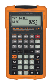
A calculator automates that process.
Enter the workpiece material, tool material and coating, cutter diameter, number of flutes, and cutting geometry. The calculator provides calculated values for:
It also provides conservative, base, and aggressive starting values so machinists can select an appropriate starting point for the application.
What the Travers Milling Calculator Covers
The calculator supports a broad range of milling applications, including:
Common machining materials include:
The calculator also accounts for tool coating and cutting conditions when establishing its starting values.
Cutter Diameter and Chip Load
Chip load generally increases as cutter diameter increases, but there is no single universal formula that determines the 
correct chip load for every milling operation.
For example, the appropriate chip load for a 1/2-inch end mill depends on the workpiece material, tool construction, number of flutes, cutter geometry, radial and axial engagement, and the rigidity of the setup.
Long tool overhangs (tool stickout), thin walls, light finishing passes, and other less-rigid conditions generally require adjustments from standard starting values.
Carbide End Mill Speeds and Feeds
Carbide end mills generally allow significantly higher cutting speeds than HSS or even Cobalt tooling, but the actual recommended SFM depends on the workpiece, carbide grade, cutter geometry, coating, and application.
For example, Travers' current reference data lists substantially different carbide cutting-speed ranges for aluminum, mild steel, alloy steel, stainless steel, and titanium.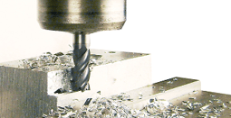
Coatings such as TiAlN and AlTiN can support higher-performance applications, but coating alone should not be treated as a universal multiplier for cutting speed.
Consider Radial Engagement
Width of cut is another important factor when selecting milling parameters.
A full-width cut places substantially different demands on the cutter than a light radial engagement. At smaller radial engagements, radial chip thinning can affect the actual chip thickness and may require an adjustment to programmed feed rate.
Practical Uses for a Milling Speeds and Feeds Calculator
■Setup Verification
Before running a new tool or material, use the calculator to establish a reasonable starting point. Compare the result with your tooling manufacturer's recommendations and your machine's capabilities.
■CNC Programming
Use calculated RPM and feed-rate values as a starting point when programming or reviewing CNC operations.
■Job Shop Quoting
Estimated material removal rates can help when calculating machining time and evaluating potential cycle times.
■Training and Education
A calculator is also useful for teaching the relationship between cutter diameter, SFM, RPM, chip load, and feed rate.
The Travers Industrial Milling Speed & Feed Calculator is free to use and requires no login.
Open the Milling CalculatorEnter your material, tool information, cutter geometry, and cutting conditions to calculate a useful starting point for your next milling operation.
What's Coming Next
Milling is one part of a larger group of machining calculations. Travers is also developing additional calculators and resources for other machining operations, including hole making, threading, and turning.
Have a calculator or machining resource you'd like to see? Let us know — or call the Travers technical team at 1-800-221-0270.
Key Takeaways
Start with an appropriate SFM for the workpiece and cutting tool. Calculate RPM from cutter diameter, then calculate feed rate using RPM, number of flutes, and chip load per tooth.
RPM = (SFM × 3.82) ÷ Cutter Diameter
IPM = RPM × Flutes × Chip Load per Tooth
The Travers calculator performs these calculations automatically.
SFM (surface feet per minute) is the speed at which the cutting edge moves across the workpiece surface — it depends on the material and tool combination. RPM is how fast the spindle turns. A smaller cutter needs higher RPM to maintain the same SFM: RPM = (SFM × 12) / (π × D).
Chip load depends on the cutter, workpiece, cutting conditions, and application. Manufacturer recommendations are the best starting point when available. For general reference, the Travers calculator provides diameter-based chip-load starting values for common materials and solid-carbide end mills.
For a conventional milling calculation:
MRR = DOC × WOC × IPM
The result is expressed in cubic inches per minute. Remember that calculated MRR does not by itself determine whether a cut is appropriate. Machine horsepower, spindle torque, tool strength, workholding, cutter engagement, and setup rigidity must also be considered.
Yes. However, indexable tooling requires particular care because recommended speeds and feeds can vary significantly between manufacturers, insert grades, chipbreaker geometries, and coatings. The Travers calculator specifically identifies its indexable-tool values as general starting points and recommends verifying them with the insert manufacturer's data.
Completely free, no login or account required. Open the page, select your parameters, and get results instantly. It runs entirely in your browser.
A printed milling speeds and feeds chart is a handy quick reference on the shop floor, but it can't adjust for your exact cutter diameter, flute count, or coating. The Travers calculator is essentially a dynamic chart — it uses the same Machinery's Handbook reference data, but calculates RPM, feed rate, and MRR for your specific setup in real time. Think of it as the chart that does the math for you.